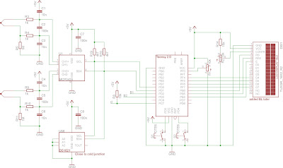
From left to right:
- Thermocouples and ADC input circuitry. The thermocouples are grounded through a $1~\mathrm{M\Omega}$ resistor (R5 and R11) before the signal goes through a filter (R3, R4, C1...C3 and R9, R10, C4...C5) and to the ADC (16 bit, MCP3426).
- Below the ADC (in the schematic and physically) is a DS1621 temperature sensor which is used for cold junction compensation. The thermocouple connection is made through screw terminals right next to the temperature sensor.
- The I2C bus has the usual $4,7~\mathrm{k\Omega}$ pullups on SCL and SDA.
- R8 is a pull-up resistor for the optocoupler used for zero-crossing detection (which is in the AC box).
- The signals B1 and B2 are outputs to the solid state relay driving transistors. The SSRs are in the AC box, the transistors are in the MCU box (but included in the AC schematic below).
- Teensy 2.0, two push buttons and a potentiometer. The buttons don't have external pull-up resistors; the AVR's internal pull-ups are used instead. The buttons and pot are used for manual control of the oven.
- 16x2 character LCD with connections for use in 4-bit mode.
Again from left to right:
- R12 and R13 are the base resistors for Q1 and Q2. I don't remember the value, but small enough to drive the transistor into saturation. Q1 and Q2 are general purpose transistors (BC547C) and sink current from K1 and K2 (Solid State Relays, S202S02), LED1 and LED2 (just to see if the SSRs are on). The SSRs are in the AC box.
- An SFH620A-3 optocoupler (OK1) used for zero-crossing detection with current limiting resistors R6 and R7. The optocoupler's output is fed to the MCU (signal C). There is a fantastic answer to the question "How do I select the accompanying components for an optocoupler?" on StackExchange.
- The oven's heaters with $P_H = 400~\mathrm{W}$ each.


No comments:
Post a Comment