2013-05-19

Same curve fit, but using levmar

Using Matlab's cftool for curve fitting is probably too expensive for home use. When I did that curve fit, I chose the Levenberg-Marquardt algorithm and applied suitable bounds for the coefficients. Suitable in this case meant that $K_0 > 0$, $K_T >0$ and $E_K > 0$. There are C++ implementations of the LMA available, such as the levmar library.

I tried to use that instead of Matlab and almost immediately got the same results for the parameters, which is great. It was as simple as taking the example that came with levmar and modifying it to suit my needs:
  • Wrote a model function that returns $T_A(P)$ in steady state;
  • Supplied the $T_A$ measurements as the measurement vector x;
  • Wrote a vector for the lower bounds (with low values for the parameters, like $0.01$);
  • Used dlevmar_bc_dif (double precision levmar with box constraints and finite difference approximated Jacobian) for solving the minimization problem;
  • As levmar has no way to directly pass inputs to the model, I passed the power settings in the additional data argument.
I could have also used inequality constraints instead, but I just started with box constraints and got satisfactory results. I might need them though when the model gets more complicated. The levmar library also offers linear equation constraints, and all (box, linear equation, and inequality) can be combined.

2013-05-13

More Measurements

After doing more measurements with power settings up to about $P = 226\,\mathrm{W}$ ($18/64$ of the total power), I came up with this set of steady states:
That's not very linear, so the simple $P=\dot{Q}=K(T_A-T_\infty)$ with a constant $K$ won't work well. Here $K=k \cdot A$ where $k$ is the overall heat transfer coefficient. $K$ needs to include a non-linear term that takes the temperature difference into account. Here is one: $$K=K_0 + K_T\left( \frac{T_A - T_\infty}{T_\infty} \right)^{E_K}$$ Let's fit that to the data (although the underlying physical model is quite coarse...). I used Matlab's cftool and a custom function, yielding the coefficients $$K_0 = 0.2072\,\mathrm{\frac{W}{K}},~K_T = 1.04\,\mathrm{\frac{W}{K}},~E_K = 0.5219$$
While this looks good, it is by far not an accurate model of the oven. The $K$ calculated above is just one temperature-dependent factor for the following phenomena:
  • natural convection between the heaters and the air in the oven,
  • natural convection between the air and the oven's inner wall,
  • radiation between the heaters and the oven's inner wall,
  • heat conduction in the insulation,
  • natural convection between the oven's outer wall and the surrounding air,
  • radiation between the oven's outer wall and any surrounding walls of the building it is in (this can be neglected I think).
No transient phenomena are modeled, but they will be important for controlling the oven. I'll try to come up with a model in OpenModelica or even write one with boost.Odeint.

2013-05-06

First Measurement

Here's a plot of the first measurement I made, and it shows a lot. The power was set to $1/64$ of the possible output, so $P = 12.5~\mathrm{W}$:

The atmosphere in the oven takes some time to reach its final value. In this case I decided that the steady state was reached after about 100 minutes. This is far too long for soldering, but the oven doesn't need to have reached a steady state at all times (that would be impossible anyway). The overall shape of the response to the step input looks like that of a second order system. I'll have too see how well I can match it with a simulation.

The measured temperature shows small fluctuations at about $1600~\mathrm{s}$ and $4000~\mathrm{s}$. These are not caused by any thermodynamic process in the oven, but by the cold junction compensation. The DS1621 has a resolution of $0.5~\mathrm{K}$ and the output jumps back and forth while the PCB heats up a bit (the enclosure is heated up by the LCD's backlight).  As this jumping value is added to the thermocouple's output, it it shows up as jumps in the measured temperature. I'll need some filtering and a better sensor next time.

I've done some more measurements with higher power settings and will add them up in another plot. With about $1/3$ power the temperature rises to about $250~\mathrm{^\circ C}$, so there's plenty of room for quickly heating it up for the reflow phase.

2013-05-01

Circuit Overview

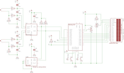
The circuit for controlling the oven is built around a Teensy 2.0 which is basically a breakout board for the ATmega32u4 microcontroller. As the heaters need mains voltage ($230~\mathrm{V}$ AC, $50~\mathrm{Hz}$), the circuit is divided into two parts: an AC part in a metal enclosure and a low-voltage DC part in a plastic enclosure. This adds some ugly and nasty cables, but I felt better doing it that way (this is my first project that involves mains voltage). This is the MCU part (you can also open the schematics page via the link shown to the right):
From left to right:
  • Thermocouples and ADC input circuitry. The thermocouples are grounded through a $1~\mathrm{M\Omega}$ resistor (R5 and R11) before the signal goes through a filter (R3, R4, C1...C3 and R9, R10, C4...C5) and to the ADC (16 bit, MCP3426).
  • Below the ADC (in the schematic and physically) is a DS1621 temperature sensor which is used for cold junction compensation. The thermocouple connection is made through screw terminals right next to the temperature sensor.
  • The I2C bus has the usual $4,7~\mathrm{k\Omega}$ pullups on SCL and SDA.
  • R8 is a pull-up resistor for the optocoupler used for zero-crossing detection (which is in the AC box).
  • The signals B1 and B2 are outputs to the solid state relay driving transistors. The SSRs are in the AC box, the transistors are in the MCU box (but included in the AC schematic below).
  • Teensy 2.0, two push buttons and a potentiometer. The buttons don't have external pull-up resistors; the AVR's internal pull-ups are used instead. The buttons and pot are used for manual control of the oven.
  • 16x2 character LCD with connections for use in 4-bit mode.
This is the AC part:

Again from left to right:
  • R12 and R13 are the base resistors for Q1 and Q2. I don't remember the value, but small enough to drive the transistor into saturation. Q1 and Q2 are general purpose transistors (BC547C) and sink current from K1 and K2 (Solid State Relays, S202S02),  LED1 and LED2 (just to see if the SSRs are on). The SSRs are in the AC box.
  • An SFH620A-3 optocoupler (OK1) used for zero-crossing detection with current limiting resistors R6 and R7. The optocoupler's output is fed to the MCU (signal C). There is a fantastic answer to the question "How do I select the accompanying components for an optocoupler?" on StackExchange.
  • The oven's heaters with $P_H = 400~\mathrm{W}$ each.
The plan is to switch the heaters on for full AC waves. The SSRs have an internal zero-crossing circuit which will only switch them on when AC crosses zero. The extra zero-crossing detection with OK1 is necessary to actually track how many full waves have been fed to the heaters.